Ideal for wind-energy applications


Overview
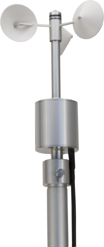
The A100LK is an anemometer suitable for your general meteorology applications and wind-energy surveys. Its low power consumption and wide power-supply range make it popular for remote locations with no access to ac power, and its pulse/frequency signal is ideal for use with Campbell Scientific data loggers. The sensor is constructed from anodized aluminum alloys, stainless steel, and weather-resistant plastics for long life. It is used as part of our WMS100 wind-monitoring system.
Read MoreBenefits and Features
- IEC Class 1 performance
- Low power consumption
- High rate of pulses per revolution produced makes it suitable for wind-surveying applications where turbulence is estimated
- Bearings protected from the entry of moisture droplets and dust, resulting in an instrument suitable for permanent exposure to the weather
Images

Detailed Description
Rotation of the A100LK’s three-cup rotor is electronically converted to pulse output signals proportional to wind speed. The A100LK produces a higher rate of pulses per revolution (up to 13) compared to relay-based sensors, making it suitable for wind surveying where turbulence needs to be estimated.
Specifications
| Sensor | 3-cup anemometer |
| Measurement Description | Wind speed |
| Signal Type/Output | Electronic pulse |
| Range | 0 to 77 ms-1 |
| Threshold | 0.15 ms-1 (starting speed 0.2 ms-1, stopping speed 0.1 ms-1) |
| Maximum Speed | 77.22 ms-1 |
| Accuracy | 1% ±0.1 ms-1 |
| Distance Constant | 2.3 m ±10% |
| Calibration Data |
Supplied for anemometer and rotor at one test speed to an accuracy of ±1% at +15°C. (12 Vdc supply and an analog output load of 1 MΩ) |
| Operating Temperature Range | -30° to +70°C |
| Rotor | 15.2 cm (6 in.) diameter three-cup rotor |
| Supply Voltage | 6.5 to 28 Vdc |
| Current Consumption |
2 mA maximum 1.6 mA typical (no output load) |
| Power-up Time | 5 s |
| Surge Protection | Vector PC3L2 anti-surge module fitted |
| Housing Diameter | 5.5 cm (2.2 in.) |
| Height | 19.5 cm (7.68 in.) |
| Weight | 490 g (17.3 oz) including 3 m (10 ft) cable |
Compatibility
Note: The following shows notable compatibility information. It is not a comprehensive list of all compatible or incompatible products.
Data Loggers
| Product | Compatible | Note |
|---|---|---|
| CR1000 (retired) | ||
| CR1000X (retired) | ||
| CR300 (retired) | ||
| CR3000 (retired) | ||
| CR310 | ||
| CR350 | ||
| CR6 | ||
| CR800 (retired) | ||
| CR850 (retired) |
Additional Compatibility Information
Data Logger Considerations
The A100LK uses one pulse count channel on the data logger.
Programming
The A100LK is read by the PulseCount Instruction in CRBasic and by Instruction 3 (Pulse Count) in Edlog. Wind speed measurements can be taken and processed with any of the data loggers.
Documents
Brochures
Manuals
Frequently Asked Questions
Number of FAQs related to A100LK: 3
Expand AllCollapse All
-
No. Cables are attached and sealed on the sensor by the manufacturer. Whenever possible, purchase a sensor with the desired cable length. Alternatively, a new sensor can be purchased with a foot of cable and then spliced onto the existing cable. Splicing cable together, however, increases the likelihood that water may enter the cable and cause shorting, corrosion, and some other potential issues, which in turn can cause measurement issues. Because of the potential issues, do not splice any sensor cable without first contacting Campbell Scientific to discuss the sensor in detail.
-
Yes. Every A100LK ships with a MEASNET calibration certificate.
-
It is possible that an older version of Short Cut is being used. Download the latest version of Short Cut.
If the latest version of Short Cut has already been downloaded, open the program.
- Go to Tools | Options and make sure that the Enable Creation of Custom Sensor Files box is checked.
- In the Generic Measurements folder, right-click the type of measurement to be made for the sensor, and select Create Custom Sensor.
- Set the fields according to the sensor’s specification, hide those fields that the user does not need to see after being set, and save the custom sensor file settings with the Save As button.
Privacy Policy Update
We've updated our privacy policy. Learn More
Cookie Consent
Update your cookie preferences. Update Cookie Preferences