6 Steps to Determine if Your Data Logger Needs Repairing
by Jason Ritter | Updated: 09/16/2015 | Comments: 2
Blog Topics
Area / Application


Product Category


Corporate / News
Search the Blog
Subscribe to the Blog
Set up your preferences for receiving email notifications when new blog articles are posted that match your areas of interest.
Suggest an Article
Is there a topic you would like to learn more about? Let us know. Please be as specific as possible.
Is your data acquisition system recording incorrect measurements, but you’re unsure of the cause? Do you wonder if your data logger may need to be repaired? This article discusses some simple tests that you can perform to help determine if your data logger has a hardware-related measurement problem and whether you need to return your data logger for repair.
We understand that it can be frustrating if you send your data logger in for repair, we tell you that we couldn't find anything wrong with it, and then you still have to pay for the repair technician's time spent testing your data logger. To avoid the cost, inconvenience, and frustration of a scenario like this, we hope this article will guide you through some self-diagnosis tests, which may point to a different underlying cause.
Note: The tests discussed in this article’s steps assume that your system is not having communications issues and that you can communicate with your data logger.
#1 - Check the power

If your data logger is not receiving enough power, it's unlikely that any other device in your data acquisition system will work properly. Issues with batteries, charge regulators, and charging sources account for a large percentage of data acquisition system failures.
As a first test, perform an independent verification of the power supply by following these steps:
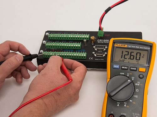
- Set your digital multimeter to the 20 Vdc range.
- Measure the voltage on the power input channels of the data logger. Most Campbell Scientific data loggers have a green two-pin screw terminal plug connector that connects to a socket labeled POWER IN.
- If your data logger does not have the two-pin connector, you will need to trace the wires from the battery to the data logger and make the measurements there.
- From the COM port on the multimeter, put the black COM probe on the terminal screw of the data logger channel labeled G or Battery.
- From the mAVΩ port on the multimeter, put the red mAVΩ probe on the terminal screw of the data logger channel labeled 12V or Battery +.
|
|
Recommended for You: For more in-depth testing of your power supply, see the "7 Steps to Determine if Your Solar-Charged Power Supply Has a Problem” blog article. |
#2 - Check the analog ground
The next step is to rule out a problem with the analog ground channels. Campbell Scientific data loggers have two types of ground channels: power ground and analog ground. The analog ground channels have a smaller, higher-resistance trace that reduces noise on the sensor voltage readings.
Normally the power ground and analog ground channels are electrically connected, but a power surge could create a break in the analog ground trace. This type of break would force the sensor signals to travel to ground through the diodes in the wiring panel, which can cause incorrect readings.
Follow these steps to identify whether there is a problem with the analog ground channels:
- Set the digital multimeter to measure resistance.
- Touch one probe to the terminal screw for any power ground (G) data logger channel.
- Touch the other probe to the terminal screw for any analog ground (AG or ⏚) data logger channel.
- You should detect a short or at least a very low resistance of less than 2 ohm. If the resistance measurement is significantly greater than 2 ohm, the data logger needs to be returned for repair.
#3 - Simplify the system
Sometimes sensors that require a power supply of more than 5 V pull the data logger out of common mode range. The easiest way to rule out this possibility is to simplify your data acquisition system by disconnecting all of the powered sensors:
- Turn off the power to the data logger.
- Using a screwdriver, disconnect all of the wires that connect the powered sensors to the data logger wiring panel. (You can identify the powered sensors by looking at the wires that are connected to a 12V or SW12 channel on the data logger and tracing them back to the sensor cables.)
- Reapply the power, and continue with the testing.
|
Tip: If you prefer, you can test both the powered and unpowered sensors:
|
#4 - Check if the data logger can measure itself
When the power test is successful, the next test is to find out if the data logger can measure its own voltages accurately. There are data logger instructions that measure the battery voltage and the panel temperature. If your data logger can’t make a good measurement of those two things, it is questionable whether it can make good measurements of your sensors.
Voltage
In this test, you send your data logger a short program that will show whether it measures voltages correctly. Whenever you send a new program to your data logger, it is generally best practice to first collect the data that is already there and to retrieve the currently running program.
Caution: Before you transmit the new program, our software will warn you that your data will be lost. That is your final reminder to save the data and the program before proceeding.
A reasonable reading for battery voltage is one that is close to what you measured with your voltmeter in the first test. Typically, the readings on the data logger and the voltmeter should be within approximately 0.2 V of each other. An unreasonable reading would be anything outside of the normal operating range of the data logger. For example, if a CR1000 datalogger is reporting a battery voltage less than 9 V or greater than 16 V, there is a problem with the data logger.
Panel Temperature
Panel temperature is reported in °C, so a reasonable value in an indoor setting might be in the range of 20° to 25°C. If your data logger is deployed in the field, you might see panel temperatures ranging from below 0°C to above 40°C, depending on the season and location.
Analog Output and Input
We also want to know if the data logger can perform analog output and analog input instructions properly. You can check this by following these steps:
- Strip the ends of a short piece of copper wire.
- Connect the wire to the single-ended channel 1 and excitation channel 1 on the data logger. (For a CR1000, this would be SE1 and VX1.)
- Program the data logger to excite with a voltage of 2500 mV.
- Measure that voltage with a single-ended input channel.
The following are example programs for testing data logger analog output and input:
'CR1000 Series Datalogger

Public PTemp, BattV, Test_mV

BeginProg
	Scan (1,Sec,0,0)
		PanelTemp (PTemp,250)
		Battery (BattV)
		ExciteV (Vx1,2500,0)
		VoltSe (Test_mV,1,mV5000,1,1,0,250,1.0,0)
	NextScan
EndProg
;{CR10X}

;

*Table 1 Program

	01: 1         Execution Interval (seconds)


1:  Batt Voltage (P10)

	1: 1        Loc [ BattV     ]


2:  Internal Temperature (P17)

	1: 2        Loc [ PTemp    ]


3:  Excite-Delay (SE) (P4)

	1: 1        Reps

	2: 15       2500 mV Fast Range

	3: 1        SE Channel

	4: 1        Excite all reps w/Exchan 1

	5: 0        Delay (0.01 sec units)

	6: 2500     mV Excitation

	7: 3        Loc [ Test_mV   ]

	8: 1.0      Multiplier

	9: 0.0      Offset
Note: If you are testing a CR200-series or CR200X-series datalogger, your test program will be similar to the CR1000 program in the example, but without the PanelTemp() instruction.
In this test, if Test_mV shows 2500 mV, the data logger is measuring properly on that input channel and output channel. There still might be an issue with a specific input channel, excitation channel, or sensor, so you might want to repeat the test by specifying other input and output channels in your test program.
#5 - Slowly reintroduce complexity
To check the sensors individually, follow these steps:
- Reload the original data logger program.
- Power down the data logger.
- Start reconnecting the powered sensors one at a time.
- After connecting each sensor, reapply power, and check to see if the readings make sense.
- If the readings are incorrect after adding a specific sensor, the sensor could be the issue, or there might be an issue with the data logger input or output channels.
- Move the sensor to another input channel and another excitation channel, and modify the data logger program to match the new wiring.
- If the incorrect readings return, the sensor is the cause. Otherwise, your data logger probably has a failing channel and should be returned for repair.
#6 - Review the results
Review the results from the previous steps to see if any of the following conditions were met when the data logger was not attached to any sensors:
- There was high resistance between the analog and power ground channels.
- The battery voltage measurement from the data logger was not consistent with the measurement from the voltmeter.
- The panel temperature was not measured.
- The data logger didn’t measure 2500 mV with the output/input test.
If any of these conditions were met, return your data logger for repair. Contact Campbell Scientific for a Return Material Authorization (RMA).
In Summary
This article featured basic troubleshooting tests to determine if your data logger has a hardware-related measurement problem that needs repairing. As a quick review, these are the steps to test your data logger:
#1 - Check the power.
If your data logger doesn’t have enough power, it can't make a good measurement.
#2 - Check the analog ground.
There should be continuity between analog ground and power ground channels.
#3 - Simplify the system.
Disconnect the powered sensors so that your data logger can be tested separately.
#4 - Check if the data logger can measure itself.
Program your data logger to measure its own battery voltage, panel temperature, and analog output/input; check if those measurement values are reasonable.
#5 - Slowly reintroduce complexity.
Reconnect the sensors one at a time, while watching the measurements to see if adding a specific sensor causes incorrect readings.
#6 - Review the results.
If the results of the previous tests indicate that there is an issue with your data logger, contact Campbell Scientific for a Return Material Authorization (RMA) so that you can return the data logger for repair.
|
We hope these steps help your troubleshooting efforts so that you can avoid unnecessarily sending in your data logger for repair. We understand the cost and inconvenience you incur when your equipment is not in the field, collecting your valuable data, and it is our desire that you return to your normal measurement operation as quickly as possible. |
Credits: Troy Sterr, Senior Electronics Technician at Campbell Scientific, Inc., contributed to this article.
Looking Ahead: Troubleshooting power issues and communications issues will be detailed in future articles.
Do you have any questions regarding data logger troubleshooting? Feel free to share them below.


About the Author
 Jason Ritter was a Senior Support and Implementation Specialist at Campbell Scientific, Inc. He worked with customers to help them make the best measurement possible. Jason was a longtime fan of Campbell Scientific, having been a customer for ten years before joining the company as an application specialist. He also held the positions of soil scientist, soils product manager, soils market manager, and product group manager.
Comments
rlwoell | 09/28/2015 at 02:46 PM
Another quick check I do if my readings seem off is to use a volt meter and measure all of the sensor input voltages. If a sensor has failed and is sending a voltage higher than the data logger's common mode voltage, other channels may be affected as well.
Notso | 09/28/2015 at 03:19 PM
Thanks, that's a good point. Common mode range is the voltage range, relative to the datalogger ground, within which both inputs of a differential measurement must lie in order to make a differential measurement. For the CR800-series, CR1000, CR3000, CR6, 21X, CR23X & CR5000 dataloggers, common mode is +/- 5 V. For the CR9000X it can be +/- 5 V, +/- 50 V, or +/- 60 V depending on the analog input card used. The CR510, CR10, & CR10X have a common mode range of +/- 2.5 V. The article mentions disconnecting sensors and slowly adding them back to the system as part of the troubleshooting, but a quick check to see if any sensors have a voltage outside the common mode range could save a lot of time.
Please log in or register to comment.