| Services Available | |
|---|---|
| Repair | Yes |
| Calibration | Yes |
| Free Support | No |
Overview
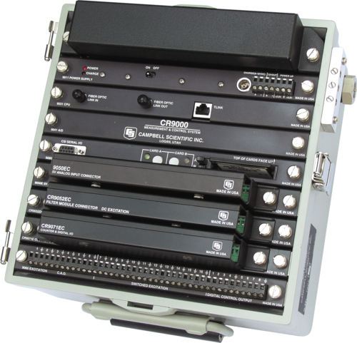
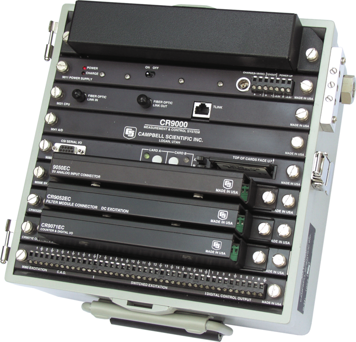
The CR9000XC, a compact version of the CR9000X, holds up to five user-selectable I/O modules. It is a modular, multiprocessor system that provides precision measurement capabilities in a rugged, battery-operated package. It consists of an environmental enclosure, a base system, and a chassis containing slots for the I/O modules.
The CR9000X series is our fastest data logger series, with a measurement rate of 100,000 Hz and a clock speed of 180 MHz, making it ideal for rapid sampling applications.
For the entire list of available I/O modules for the CR9000XC and CR9000X, visit the Other Accessories section of the Ordering Info page for the CR9000XC and the CR9000X.
Campbell Scientific also offers the CR9000X, a larger version, that accepts up to nine I/O modules. For more information, visit the CR9000X Product Info page.
Read MoreBenefits and Features
- Up to five I/O modules can be used to configure a system for your specific application.
- Ideal for vehicle testing, structural or seismic monitoring, or other applications that require rapid sampling or a large number of high resolution channels
- Throughput of 100,000 measurements per second is ideal for high demand research, such as flux and complex structural monitoring.
- Contains an on-board 10baseT/100baseT port allowing direct Ethernet connection; an interface such as the NL100 is not required
- CR9052IEPE and CR9052DC modules provide powerful anti-aliasing and real-time FFT capabilities that are unique to the CR9000X-series dataloggers
- Integrated PCMCIA slot accepts memory cards up to 2 GB for stand-alone data collecting.
- Gas Discharge Tube (GDT) protected inputs
- Collects and stores data and controls peripherals as the brain of your system
Images
Detailed Description
The CR9000XC's base system includes a CR9032 CPU module, CR9041 A/D module, CR9011 power supply module, and 128-Mbytes SDRAM memory for program and data storage. The CR9000XC's internal battery has a 7-Ahr capacity.
A mix of I/O modules is selected based on the measurements required for the application. Campbell Scientific offers a large variety of modules. Individual I/O modules can be swapped out, allowing the system to be reconfigured if requirements change.
I/O modules whose model numbers end in an E (e.g., CR9051E, CR9055E) and the CR9052DC include an easy connector module. Easy connector modules allow sensor wiring to remain connected while the input module’s measurement electronics and the rest of the data logger system are used elsewhere.
The CR9000XC includes a non-corrosive, sealed, aluminum enclosure that provides protection from water, dust, and most environmental pollutants.
CR9000XC versus CR9000C
In August 2004, the CR9000XC replaced the CR9000C. The CR9000C and CR9000XC dataloggers differ in their CPU Module; the CR9000C datalogger uses the CR9031 and the CR9000XC datalogger uses the CR9032.
The CR9032 CPU module supports a measurement rate of up to 100,000 Hz, provides a 180 MHz clock speed, and adds a built-in RS-232 port, 10baseT/100baseT port, CS I/O port, and PC-card slot. The built-in ports enable communication without using the special interfaces (e.g., PLA100, TL925, NL105) that were required for the retired CR9000C datalogger. The PC-card slot allows the CR9000XC to store data on a Type I, Type II, or Type III PCMCIA card, or on a CompactFlash® card if an adapter is used.
An existing CR9000C datalogger may be upgraded to a CR9000XC by replacing the CR9031 CPU module with the CR9032 CPU module.
Specifications
| -NOTE- |
|
| Operating Temperature Range |
|
| Analog Inputs | 28 single-ended or 14 differential per CR9050, CR9051E, or CR9055(E) module |
| Pulse Counters | 12 per CR9071 module |
| Communications Ports |
|
| Switched 12 Volt | 1 |
| Digital I/O |
|
| Analog Voltage Accuracy | ±(0.07% of reading + 4 A/D counts), -25° to +50°C |
| ADC | 16-bit |
| Power Requirements | 9.6 to 16 Vdc |
| Communication Protocols | SDM |
| Warranty | 3 years |
| Dimensions | 25.4 x 27.9 x 22.9 cm (10 x 11 x 9 in.) |
| Weight | 12.3 kg (27 lb) with modules |
Compatibility
Note: The following shows notable compatibility information. It is not a comprehensive list of all compatible or incompatible products.
Software
| Product | Compatible | Note |
|---|---|---|
| LoggerNet | Version 2.0 or higher | |
| PC200W (retired) | ||
| PC400 | Version 1.0 or higher | |
| RTDAQ | Version 1.0 or higher | |
| Short Cut | ||
| VISUALWEATHER - Retired (retired) | Version 2.0 or higher |
Additional Compatibility Information
Compatibility with Retired Products
Customers can add CR9000XC dataloggers to networks containing the older CR9000 or CR9000C dataloggers. I/O modules other than the CR9080 can be used with either the CR9000 series or CR9000X series. CR9000 series communication interfaces (i.e., NL105, BLC100, TL925, PLA100) are not compatible with the CR9000XC, and therefore have been retired. RTDAQ software is not compatible with the older CR9000(C). Customers can upgrade a CR9000C datalogger to a CR9000XC datalogger by replacing the CR9000C's CR9031 CPU module with the contemporary CR9032C CPU module.
Sensors
With several channel types, the CR9000XC is compatible with many sensors, including thermocouples and 4 to 20 mA sensors.
Measurement and Control Peripherals
Measurement and control peripherals typically used with the CR9000XC are our AM25T 25-Channel Solid State Multiplexer, SDM-CAN Interface, SDM-INT8 Eight Channel Interval Timer, and SDM-SIO4 Serial Input/Output Module. Other measurement and control peripherals are compatible but they do not support the CR9000XC datalogger's maximum measurement rate and are therefore impractical for most CR9000XC applications.
Communications
The CR9000XC typically communicates with a PC via direct connect or Ethernet. Because the CR9000XC has an on-board 10baseT/100baseT port, an Ethernet interface such as the NL100 is not required.
Storage capacity can be increased by using a PC or CompactFlash card. The CR9000XC's PCMCIA card slot supports one Type I, Type II, or Type III PC Card or the CF1 adapter and one CompactFlash (CF) card.
The storage capacity of Type II cards exceeds 1 GB. Type III cards provide data storage capacities exceeding 1 GB but may not be suitable for all environments. Campbell Scientific offers CF cards that store up to 2 GB of data. Please note that the PCMCIA and CompactFlash cards need to be industrial-grade and have a storage capacity of 2 GB or less.
Other communication peripherals are compatible but they do not support the CR9000XC datalogger's maximum measurement rate and are therefore impractical for most CR9000XC applications.
Enclosures
The CR9000XC includes a non-corrosive, sealed, aluminum enclosure that provides protection from water, dust, and most environmental pollutants.
Software
CRBasic, the CR9000XC's full programming language, supports simple or complex programming and many on-board data reduction processes. CRBasic is included in RTDAQ, LoggerNet, and PC400.
RTDAQ Real-Time Data Acquisition Software must be ordered separately; the CR9000XC is also compatible with other Campbell Scientific software.
Documents
Brochures
Technical Papers
Frequently Asked Questions
Number of FAQs related to CR9000XC: 32
Expand AllCollapse All
-
The CR3000 program will have to be modified so that each measurement or control instruction includes the appropriate module number. Some parameters might differ as well.
-
Yes. The simplest method is to use conditional program statements that execute most of the code based on time. For example, the data could be scheduled to log at 6 a.m. and finish at 8 p.m. using CRBasic instructions such as TimeIntoInterval(). Another option is to use an IfThen/EndIf construction that does a logical test of light-level measurements based on a light sensor. An additional option is to use calculated sunrise and sunset times along with a combination of RealTime() and Case instructions.
For more information, see the “Decisions, Decisions, Decisions…” article.
-
If small amounts of data are transferred per transmission, it will not be a problem. Larger amounts of data can overrun buffers in the modem, causing lost data. In that situation, lower the baud rate on the data logger to avoid the issue.
-
Common causes include the following:
- Loss of power to the data logger and the program Run On Power-up attribute not being set (For help with this, see the “How Do You Run?” article.)
- A FillStop instruction in a CRBasic program used to set data tables to stop storing new data when full
- Logical conditions for writing to data tables that do not evaluate as TRUE
-
The maximum cable length depends on the interface being used.
- RS-232 connections will reach 15 m (50 ft).
- RS-485 connections go beyond 610 m (2,000 ft).
- IP connections can be routed worldwide.
-
The data logger will not reset the SW12 unless it is done under program control using the SW12() or PortSet() instructions, or unless the data logger compiles or recompiles a program. This could be done when a new program is sent to the data logger, or if the power is cycled.
-
Some Campbell Scientific sensors with an RS-232 output are supported in Short Cut. Because of the large variety of serial data formats, other sensors require creating a program in the CRBasic Editor. CRBasic Editor is included in several of the purchased software packages, such as LoggerNet. For more information, see the “Interfacing Serial Sensors with Campbell Scientific Dataloggers” application note.
-
A data logger can be programmed to initiate data transfer by using the SendVariables() or ModemCallback() instruction in CRBasic.
NOTE: These instructions are not supported in the CR200X operating system.
-
No, because it would not work. The SC32B is used to do the following:
- Convert data logger logic levels (on the CS I/O port) to RS-232 levels
- Optically isolate the data logger from the RS-232 peripheral
-
The available COM ports listed in the COM Port drop-down menu are supplied to PC400 by the Windows Operating System (OS). If there are no COM ports shown for selection, it most likely means that there are no COM ports registered with the Windows OS. This can be confirmed using the Windows Device Manager (Control Panel | Device Manager | Ports).
Most modern laptops are not equipped with native RS-232 COM ports. In this situation, a USB-to-RS-232 adapter cable must be used to connect to the data logger. Even when the drivers for this device have been properly installed, the derived COM port will not be shown for selection until the cable is attached to the laptop.
Privacy Policy Update
We've updated our privacy policy. Learn More
Cookie Consent
Update your cookie preferences. Update Cookie Preferences