Ideal for long-term, unattended applications


Overview
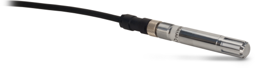
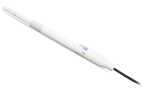
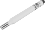
The HMP60, manufactured by Vaisala, probe measures air temperature for the range of -40° to +60°C, and relative humidity for the range of 0 to 100% RH. It uses the INTERCAP® capacitive RH chip. This field-replaceable chip eliminates the downtime typically required for the recalibration process.
Benefits and Features
- Field-replaceable humidity chip eliminates recalibration downtime
- Compatible with most Campbell Scientific dataloggers
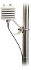
- Can be mounted to a tower/tripod mast or crossarm
Images

Specifications
| Supply Voltage | 5 to 28 Vdc (typically powered by datalogger’s 12 V supply) |
| Current Consumption |
|
| Filter Description | 0.2 µm Teflon membrane |
| Settling Time | 1 s |
| Housing Classification | IP65 |
| Housing Material | AISI 316 stainless steel |
| Filter Cap Material | Chrome-coated ABS plastic |
| Field-Replaceable Chip or Recalibrate | Field-replaceable chip (RH only) |
| Sensor Diameter | 1.2 cm (0.5 in.) |
| Filter Diameter | 1.2 cm (0.5 in.) |
| Length | 7.1 cm (2.8 in.) |
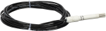
| Weight | 0.05 kg (0.1 lb) with 1.83 m (6 ft) cable |
Relative Humidity |
|
| Sensing Element | Vaisala’s INTERCAP capacitive chip |
| Measurement Range | 0 to 100% RH (non-condensing) |
| Typical Accuracy at -40° to 0°C |
|
| Typical Accuracy at 0° to 40°C |
|
| Typical Accuracy at 40° to 60°C |
|
| Output Signal Range | 0 to 1 Vdc |
Air Temperature |
|
| Sensing Element | 1000 ohm Platinum Resistance Thermometer (PRT) |
| Measurement Range | -40° to +60°C |
| Accuracy | ±0.6°C |
| Output Signal Range | 0 to 1 Vdc |
Compatibility
Note: The following shows notable compatibility information. It is not a comprehensive list of all compatible or incompatible products.
Data Loggers
| Product | Compatible | Note |
|---|---|---|
| CR1000 (retired) | ||
| CR1000X (retired) | ||
| CR300 (retired) | ||
| CR3000 (retired) | ||
| CR310 | ||
| CR350 | ||
| CR6 | ||
| CR800 (retired) | ||
| CR850 (retired) |
Additional Compatibility Information
Mounting
When exposed to sunlight, the HMP60 must be housed in a 41303-5A, 41303-5B, or RAD06 6-plate naturally aspirated radiation shield. The 41303-5A and RAD06 attaches to a crossarm, mast, or user-supplied pipe with a 2.5 to 5.3 cm (1.0 to 2.1 in.) outer diameter. The 41303-5B attaches to a CM500-series pole or a user-supplied pole with a 5.1 cm (2.4 in.) outer diameter.
The RAD06 uses a double-louvered design that offers improved sensor protection from driving rain, snow, and insect intrusion, It also has lower self-heating in bright sunlight combined with higher temperatures (> 24°C [~75°F]) and low wind speeds (< 2 m s-1 [~4.5 mph]), giving a better measurement.
Documents
Frequently Asked Questions
Number of FAQs related to HMP60: 5
Expand AllCollapse All
-
The HMP60 (with the Campbell Scientific cable) cannot be used with the 41003-5 10-Plate Radiation Shield without the use of additional hardware. For more information, refer to the Compatibility information on the HMP60 product page. The standard radiation shield for the HMP60 is the 41303-5A.
-
In general, the element should be replaced every two years. By doing a field check (that is, comparing the RH reading with a reference), the element can be used until the relative humidity measurement is out of tolerance.
-
The most significant difference is that the CS215 has an SDI-12 output and that the HMP60 has a voltage output. Additional differences are outlined in the “Air Temperature & Relative Humidity” brochure, which compares all of the Campbell Scientific temperature and relative humidity sensors.
-
Note the difference between calibration and a field check. Calibration cannot be done in the field, as it requires an experienced technician and specialized equipment.
Field checks of measurements can be done to determine if the data make sense with the real-world conditions. Follow these steps to field check a sensor:
- Find a second sensor of the same type as the installed sensor whose data is in question. The second sensor will be used as a benchmark sensor and should be known to be accurate or recently calibrated.
- At the site, take readings using both sensors under the same conditions. The best practice is to measure both sensors side-by-side at the same time. Note that the sensors will never have the exact same measurement.
- Depending on the sensor model, if the difference in the readings of the installed and benchmark sensors is greater than the sum of the accuracies for both sensors, either return the installed sensor to Campbell Scientific for calibration or replace the appropriate chip.
- The 107, 108, 109, 110PV-L, and BlackGlobe-L temperature sensors can be calibrated.
- The HC2S3-L and HMP155A-L temperature and relative humidity sensors can be calibrated.
- The CS215-L has a replaceable chip for temperature and relative humidity. For more information, refer to the “Maintenance and Calibration” section of the CS215 instruction manual.
- The HMP60-L has a replaceable chip for relative humidity only. For more information, refer to the “Maintenance” section of the HMP60 instruction manual.
-
To incorporate a sensor that is compatible with wireless sensor interfaces into a wireless network, a CWS900-series wireless sensor interface is needed, as well as an A205 CWS-to-PC interface to configure it.
Privacy Policy Update
We've updated our privacy policy. Learn More
Cookie Consent
Update your cookie preferences. Update Cookie Preferences