LW110 Lightning Warning System
Lighnting Warning System
Lifesaving warning before lightning strikes
weather applications water applications energy applications gas flux and turbulence applications infrastructure applications soil applications

Overview

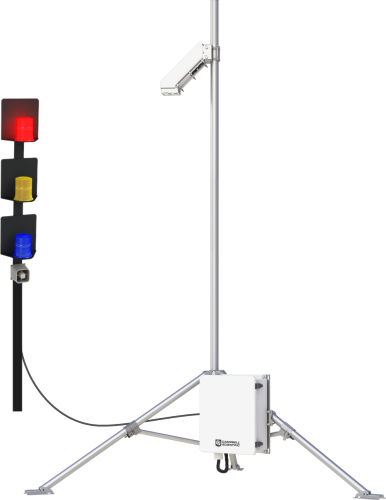
The LW110 provides continuous monitoring of the local electric field and triggers warnings when there is the potential for lightning. Because warnings are based on measurements of electric field, instead of prior strikes, the system can detect lightning danger, even when no other strikes have occurred.

By measuring the electric field at your location, the LW110 can be relied upon to remove the guesswork from critical decisions: when to seek shelter as a storm approaches, and when it’s safe to resume activities as a storm passes.

The LW110 is customizable, allowing you to add a lightning strike detector, meteorological sensors, and various communication, power, and mounting options.

Benefits and Features

  • First strike warning--senses potential for lightning
  • "All clear" notices when lightning threat has passed
  • Up to 7 mile detection radius
  • Visual and audible alarms
  • PC, web, and email alarms when communication is added
  • Optional SG000 detects strikes up to 20 mile radius and can be added to create a complete lightning-threat measurement and analysis system
  • Optional meteorological sensors for expanded weather monitoring and logging
  • Rugged construction
  • Low power consumption
  • Low maintenance—extensive diagnostics let you know when maintenance is needed

See how one of our systems is helping keep events at Utah schools safe from lightning on KSL.com.

Images

Compatibility

IMPORTANT!
The CS110 and an embedded CR1000M datalogger module (ordered as pn 18292) are required for every LW110 purchased; see Common Accessories in ordering information.

Generally, the CS110 should be run with the latest released CR1000 operating system (OS) available via "Support" on this website. However, CR1000 OS version 27.05 should NOT be downloaded to standard CS110s. OS version 27.05 was built to accommodate the ~40,000 v/m efields measured on ocean buoys. The special OS also requires a capacitor change on the CS110 panel board.

The CS110 should not be run with OS 28 (CR1000.Std.28.obj). A bug in OS 28 prevents changing the setup "Constants" via the keyboard or the terminal emulator.

Documents


Frequently Asked Questions

Number of FAQs related to LW110: 6

Expand AllCollapse All

  1. The CS110 and the tower should be positioned away from each other a distance of three times the tower’s height.

    If the radio signal is strong enough, the SG000 may pick it up as one of the two components the SG000 measures to detect lightning. If this signal coincides with a light flash from a windshield or headlight, it could generate a false strike signal. Also, constant bombardment of the SG000 by sufficiently strong RF signals will pull the sensor out of its quiescent state, affecting its current drain. This will eventually degrade the battery and shorten its expected four-year lifespan.

  2. To simulate a lightning strike to the SG000, use a camera flash to flash the glass bulb from a distance of 5.08 to 7.62 cm (2 to 3 in.). Note: A flash from a cell phone usually isn't large enough to simulate a lightning strike. 

    To simulate high electric fields on the CS110, run a comb through your hair and hold it a distance of 2.54 to 5.98 cm (1 to 2 in.) from the shutter of the CS110. Other items such as plastic bags or balloons, or fur on glass, can be used as well.

  3. The FC100 is required to communicate with the SG000 Strike Guard Lightning Sensor. The SG000 is an option for the CS110 Electric Field Sensor and the LW110 Lightning Warning System.
  4. Most Campbell Scientific sensors are available as an –L, which indicates a user-specified cable length. If a sensor is listed as an –LX model (where “X” is some other character), that sensor’s cable has a user-specified length, but it terminates with a specific connector for a unique system:

    • An –LC model has a user-specified cable length for connection to an ET107, CS110, or retired Metdata1.
    • An –LQ model has a user-specified cable length for connection to a RAWS-P weather station.

    If a sensor does not have an –L or other –LX designation after the main model number, the sensor has a set cable length. The cable length is listed at the end of the Description field in the product’s Ordering information. For example, the 034B-ET model has a description of “Met One Wind Set for ET Station, 67 inch Cable.” Products with a set cable length terminate, as a default, with pigtails.

    If a cable terminates with a special connector for a unique system, the end of the model number designates which system. For example, the 034B-ET model designates the sensor as a 034B for an ET107 system.

    • –ET models terminate with the connector for an ET107 weather station.
    • –ETM models terminate with the connector for an ET107 weather station, but they also include a special system mounting, which is often convenient when purchasing a replacement part.
    • –QD models terminate with the connector for a RAWS-F Quick Deployment Station.
    • –PW models terminate with the connector for a PWENC or pre-wired system.
  5. Not every sensor has different cable termination options. The options available for a particular sensor can be checked by looking in two places in the Ordering information area of the sensor product page:

    • Model number
    • Cable Termination Options list

    If a sensor is offered in an –ET, –ETM, –LC, –LQ, or –QD version, that option’s availability is reflected in the sensor model number. For example, the 034B is offered as the 034B-ET, 034B-ETM, 034B-LC, 034B-LQ, and 034B-QD.

    All of the other cable termination options, if available, are listed on the Ordering information area of the sensor product page under “Cable Termination Options.” For example, the 034B-L Wind Set is offered with the –CWS, –PT, and –PW options, as shown in the Ordering information area of the 034B-L product page.

    Note: As newer products are added to our inventory, typically, we will list multiple cable termination options under a single sensor model rather than creating multiple model numbers. For example, the HC2S3-L has a –C cable termination option for connecting it to a CS110 instead of offering an HC2S3-LC model. 

  6. Many Campbell Scientific sensors are available with different cable termination options. These options include the following:

    • The –PT (–PT w/Tinned Wires) option is the default option and does not display on the product line as the other options do. The cable terminates in pigtails that connect directly to a data logger.
    • In the –C (–C w/ET/CS110 Connector) option, the cable terminates in a connector that attaches to a CS110 Electric Field Meter or an ET-series weather station.
    • In the –CWS (–CWS w/CWS900 Connector) option, the cable terminates in a connector that attaches to a CWS900-series interface. Connection to a CWS900-series interface allows the sensor to be used in a wireless sensor network.
    • In the –PW (–PW w/Pre-Wire Connector) option, the cable terminates in a connector that attaches to a prewired enclosure.
    • In the –RQ (–RQ w/RAWS Connector) option, the cable terminates in a connector that attaches to a RAWS-P Permanent Remote Automated Weather Station.

    Note: The availability of cable termination options varies by sensor. For example, sensors may have none, two, or several options to choose from. If a desired option is not listed for a specific sensor, contact Campbell Scientific for assistance.

Case Studies

U.S. PGA Tour: Lightning Warning System
The Professional Golfers’ Association Tour (PGA Tour) of America contracted with Schneider Electric to provide......read more
Utah: Lightning Warning at Schools
Lightning strikes are a serious concern for school officials who are responsible for protecting the......read more
Peru: Lightning in the Highlands
Lightning kills about 40 people a year in the highland areas of Peru. This startling......read more

Privacy Policy Update

We've updated our privacy policy.  Learn More

Cookie Consent

Update your cookie preferences.  Update Cookie Preferences