This product is not available for new orders.

| Services Available | |
|---|---|
| Repair | Yes |
| Calibration | Yes |
| Free Support | Yes |
Overview
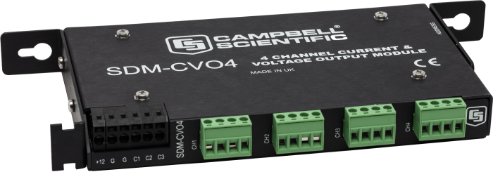
The SDM-CVO4 is attached to a data logger and outputs variable voltage or current signals under data logger program control. Typical applications include driving remote current-loop display units, retransmitting measured values to industrial control systems, sending control signals to valve controllers, and providing excitation voltages or currents to external sensors.
Read MoreBenefits and Features
- Expands data logger current/voltage output capability
- Provides four independent current or voltage outputs
- Drives remote current-loop display units
- Retransmits measured values to industrial control systems that have current or high voltage inputs
- Sends control signals to valve controllers
- Provides excitation voltages or currents to external sensors
The SDM-AO4A can be used as a replacement for the SDM-CVO4 except when isolated voltage or current outputs are needed.
Images

Detailed Description
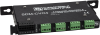
The SDM-CVO4 includes four output channels for connecting the external devices. It outputs variable voltage or current signals under data logger program control. The outputs are isolated both from the data logger and the other channels on the SDM-CVO4, thereby avoiding ground loop problems. Each output can be set to 0 to 10 Vdc or 0 to 20 mA by the data logger program. (Current outputs can also be scaled and limited to 4 to 20 mA.)
In the current mode, the output either acts as a two-wire current controller, where the loop is powered from a remote voltage source, or generates a 0 to 20 mA current source using a voltage output derived from its own power supply.
Isolation
The SDM-CVO4 includes an internal isolation barrier and components rated to provide signal isolation for transients up to 1500 Vac (rms), 2500 Vdc nominal. The isolation is between any output and the SDM-CVO4 ground connection and between individual output channels.
Protection components are built-in, which will break down in a controlled fashion at voltages close to this limit. (See the Instruction Manual, Section 4.5 Safety Considerations, for details).
Specifications
| Function | Expands data logger current/voltage output capability. |
| Number of Channels | 4 |
| Operating Temperature | -25 to +50°C |
| Operating Voltage | 12 Vdc nominal (8 to 16 V) |
| Minimum Voltage Drop | 2.5 V (@ 20 mA current flow) across the internal current regulating circuit |
| Maximum Input Voltage | 20 Vdc (relative to channel ground) |
| EMC Status | Complies with EN55022-1:1998 and EN50082-1:1998. |
| Dimensions |
|
| Weight | 363 g (13 oz) |
Isolation |
|
| Tested Isolation |
Each channel of each unit is tested for isolation resistance at 500 Vdc. Pass level > 10 MΩ |
| Maximum Recommended Continuous Operating Voltage | 240 Vac rms differential between an output and data logger ground, providing all issues relating to local regulations for safe installation and operation are followed (Refer to Section 4.5 Safety Considerations in the Instruction Manual.) |
Current Mode |
|
| Range | 0 to 20,000 µA |
| Resolution | 5 µA |
| Minimum Output Current (leakage) | 5 µA (at +50°C) |
| Accuracy at +23°C | ±0.02% of set current + (±5 µA) |
| Typical Accuracy at -25° to +50°C | ±0.1% of set current + (±5 µA) |
| Worst Case Accuracy at -25° to +50°C | ±0.15% of full scale range + (±5 µA) |
Voltage Mode |
|
| Range | 0 to 10,000 mV |
| Resolution | 2.5 mV |
| Maximum Output Current | 30 mA per channel |
| Minimum Load Current | 5 µA if output < 200 mV |
| Accuracy at +23°C | ±0.02% of set voltage + (±2.5 mV) |
| Accuracy at -25° to +50°C | ±0.13% of set voltage + (±2.5 mV) |
Current Drain @ 12 Vdc |
|
| Typical Active Current |
27 or 54 mA, depending on operating mode (no load on output ports) To estimate the total current, add the active current to the sum of all output currents multiplied by 1.5. For example, if each port is at 10 mA output, the total = 54 + (1.5•4•10) = 114 mA. |
| With All Outputs Off | < 0.5 mA |
Compatibility
Note: The following shows notable compatibility information. It is not a comprehensive list of all compatible or incompatible products.
Data Loggers
| Product | Compatible | Note |
|---|---|---|
| 21X (retired) | ||
| CR10 (retired) | ||
| CR1000 (retired) | ||
| CR1000X (retired) | ||
| CR1000Xe | ||
| CR10X (retired) | ||
| CR200X (retired) | ||
| CR206X (retired) | ||
| CR211X (retired) | ||
| CR216X (retired) | ||
| CR23X (retired) | ||
| CR295X (retired) | ||
| CR300 (retired) | ||
| CR3000 (retired) | For the CR3000, SDMs are connected to the ports labeled SDM-C1, SDM-C2, and SDM-C3. | |
| CR310 | ||
| CR500 (retired) | ||
| CR5000 (retired) | For the CR5000, SDMs are connected to the ports labeled SDM-C1, SDM-C2, and SDM-C3. | |
| CR510 (retired) | ||
| CR6 | ||
| CR800 (retired) | ||
| CR850 (retired) | ||
| CR9000 (retired) | Although the CR9000 is compatible, the SDM-CVO4 does not support its fastest communication rates and therefore may not be practical for CR9000 applications. | |
| CR9000X (retired) | Although the CR9000X is compatible, the SDM-CVO4 does not support its fastest communication rates and therefore may not be practical for CR9000X applications. | |
| Granite 9 |
Mounting Equipment
| Product | Compatible | Note |
|---|---|---|
| ENC10/12 | ||
| ENC10/12R | ||
| ENC12/14 | ||
| ENC14/16 | ||
| ENC16/18 | ||
| ENC24/30 | ||
| ENC24/30S |
Miscellaneous
| Product | Compatible | Note |
|---|---|---|
| Granite 10 | ||
| Granite 6 (retired) |
Additional Compatibility Information
Programming/Software
The SDMCVO4 instruction controls the SDM-CVO4 operation in CRBasic; Instruction 103 controls the SDM-CVO4 operation in Edlog.
Power Considerations
The SDM-CVO4 power requirements are large compared to most Campbell Scientific products—especially when driving significant loads. Care must be taken to ensure the power supply can deliver this higher demand. Alkaline batteries are not recommended for long-term applications.
The SDM-CVO4 has two internal power supplies—one for channels 1 and 2, and one for channels 3 and 4. The power supply for channels 3 and 4 is only turned on if the data logger sends an instruction that sets the output of those channels. If channels 3 and 4 are not used, the power consumption is approximately 20 mA lower than when all outputs are used.
Where supported by the data logger, and when the application allows it, the SDM-CVO4 can be shut down to reduce its power consumption to less than 0.5 mA. In this state, all outputs are switched off.
Enclosure Considerations
The SDM-CVO4 requires a desiccated, non-condensing environment; a Campbell Scientific enclosure is recommended. A mounting bracket, grommets, and screws attach the SDM-CVO4 to the backplates of a Campbell Scientific enclosure.
Documents
Frequently Asked Questions
Number of FAQs related to SDM-CVO4: 5
Expand AllCollapse All
-
The SDM-CVO4 allows most Campbell Scientific data loggers to produce a value by whatever means measured or derived as a scaled 0 to 20 or 4 to 20 mA signal (four terminals).
The data logger sends an instruction to the SDM-CVO4 with the voltage or current to be transmitted to the other device. The SDM-CVO4 does not itself convert a voltage to a current. A data logger is needed to make a measurement and instruct the SDM-CVO4 as to what the output should be.
-
Yes. Up to 15 SDM devices can be attached to a data logger because they are addressable with a hex number of 0 to F. Some of those devices may require more power, which would need to be considered when adding devices.
-
For the CR1000, to get continuous analog outputs, an SDM-AO4A (4-channels, non-isolated, voltage only) or an SDM-CVO4 (4-channels, isolated, voltage or current) is needed. Multiples of these devices can be used to get more outputs. For single channels of output, some third-party devices can be used.
-
Yes. The CR3000 and CR5000 have two native Continuous Analog Output channels. The SDM-AO4A (voltage) or SDM-CVO4 (voltage or current) can also be used.
-
To get continuous analog outputs, either the SDM-AO4A (four channels, non-isolated, voltage only) or the SDM-CVO4 (four channels, isolated, voltage or current) is needed. Multiples of those devices can be used to acquire more outputs.
Case Studies
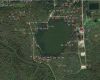
In August 2012, RESPEC was contracted to provide field instrumentation and early-warning monitoring services at......read more
In 2010, Trenton and Amalga, two northern Utah towns separated by only a few miles,......read more
Privacy Policy Update
We've updated our privacy policy. Learn More
Cookie Consent
Update your cookie preferences. Update Cookie Preferences